Objects and parts
Color-coded views show individual objects and parts within each reconstructed scene.
From a photograph to a world you can edit, interact with and manipulate.
Reconstruct editable, interactive 3D environments from photographs, with spatial relationships, internal structures and moving parts that support manipulation in simulation.
Choose a scene to explore its structure and motion.
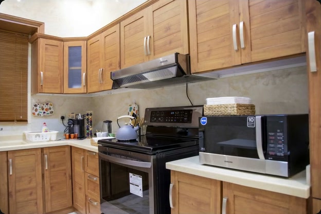
Cabinet doors swing open, drawers slide out, and the microwave and oven doors reveal their interiors.
Doors rotate about hinges. Drawers follow a sliding direction. Objects fall, collide and come to rest. Structure and physical properties shape how a scene responds to interaction.
Color-coded views show individual objects and parts within each reconstructed scene.
Hinges and sliding joints define how a part moves and its range of motion.
Mass, friction and collision geometry provide the simulation with the properties needed for contact and motion.
Change a wooden tabletop to marble or a pendant lamp to brass with a text instruction. Objects can be edited individually within the reconstructed scene.
Tell us about your target environment and the interactions you want to simulate.
Technical foundations
Object reconstruction and part generation provide a structural foundation for actionable 3D environments. Scale calibration, physical properties and simulation checks prepare scenes for specific interaction tasks.
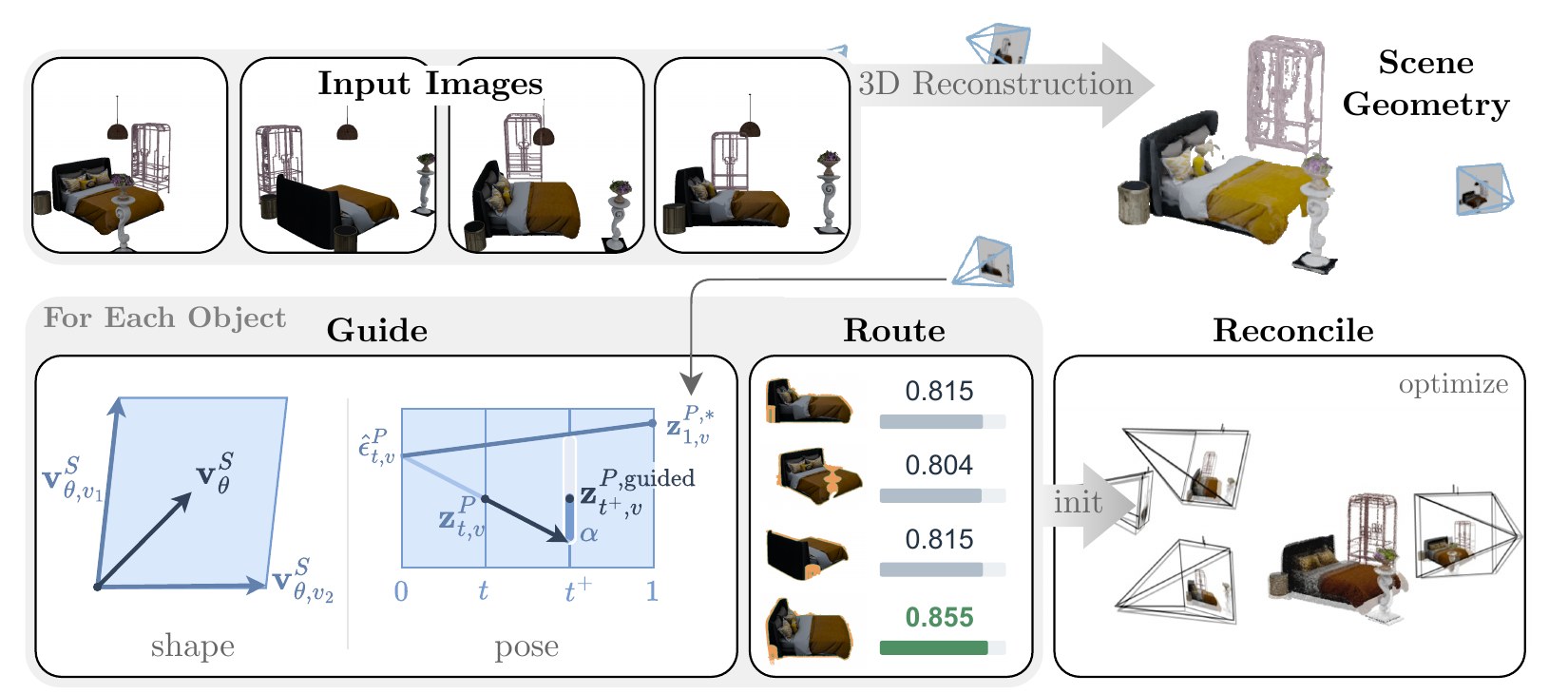
CUPID jointly estimates object geometry and camera pose, using image-aligned features to preserve observed detail. SPOON uses multi-view geometry to coordinate object scale, position and orientation in a coherent scene. Together, these research directions address fidelity to observations and the spatial arrangement of objects.
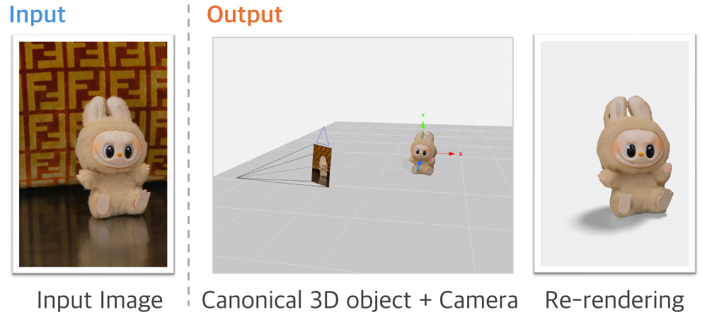
Re-rendering from the recovered camera pose checks fidelity to visible evidence. Regions outside the photograph are completed by the model and can be checked against additional views.
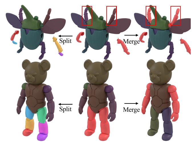
STRUCTPARTS alternates between part-local and object-global coordinates to preserve fine geometry and the arrangement of parts. Changing the segmentation groups allows parts to be split or merged. Explicit parts provide a basis for assigning joints and motion limits.
A scene intended for robot manipulation needs to be tested in simulation. The team’s workflow brings scale calibration, part modeling, physical properties and simulation checks together, using the results to validate structure and motion.
Use structural lines and objects with known dimensions as references, then cross-check the scale against other standard objects.
Align objects to shared planes such as walls, counters and cabinet fronts, while keeping doors and drawers as separate parts.
Assign hinges, sliding joints and motion limits to moving parts, and estimate object mass from material.
Compare rendered views with the input photograph. Check stability, full part motion and interpenetration in MuJoCo, followed by an independent validation pass.